- �綯��ѹ��ϵ��
- �綯��ѹ��2D-SY
- �綯��ѹ��3D-SY
- �綯��ѹ��4D-SY
- ����ʽ�綯��ѹ��
- ����ѹ�綯��ѹ��
- �綯��ѹ��2DSY��
- �綯��ѹ��2D-SY
- �綯��ѹ��3DSY��
- ��ѹ��3D-SYС��
- �綯��ѹ��3D-SY��
- �綯��ѹ��4DSY��
- �綯��ѹ��4D-SY
- �綯��ѹ��4D-SY��ʽ
- �������綯��ѹ��
- �������綯��ѹ��
- ����ѹ�綯��ѹ��
- ����ѹ�綯��ѹ��
- ������ѹ��QY140
- ������ѹ�õ���
- ������ѹ��QY140
- ������ѹ��QY140A
- ��ʽQY������ѹ��
- ������ѹ��QST��
- ������ѹ��QSTϵ��
- ������ѹ̨QSTϵ��
- ������ѹ�ó���ѹ
- Һѹ��������̨
- ������Զ�̿���װ��
- ��ѹ������¼��
- ��ѹ�����Ա�ʽ
- ��ѹ�����Լ�¼��
- �����������ѹ��
- �����������ѹ��
- ��Яʽ�������ѹ��
- ѹ���Կ���ѹ��ң��
- ��ѹ��ѹ���Կ�ң��
- ��Ƶ��������ѹ��
- ��ѹ�ò��ͻ����ͻ�
- ���ͻ����ͻ���ѹ��
- �綯��ѹ��װ���ۺ�
- ������Զ�̿���װ��
- ��ѹ�ÿ���ϵͳ���
- ��ѹϵͳ��������
- ��ѹ��ѹ�����ɷ�
- ��������ϵͳ
- ������ʾ�DZ�
- ��ѹ�ÿ�����
- �ֶ���ѹ�õ���˫��
- �ֶ���ѹ��˫��
- �ֶ���ѹ�õ���
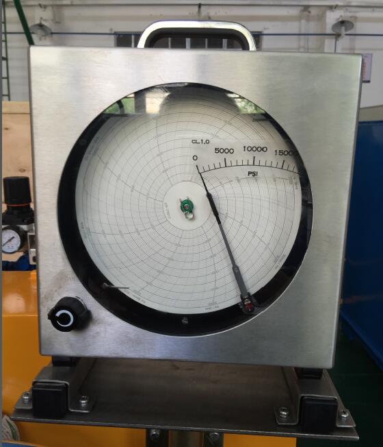
��ѹ��Բ�̼�¼��ʹ��˵����
��Դ����վ ����ʱ�䣺2016/9/13 15:27:08
��ѹ��Բ�̼�¼��ʹ��˵����
Chart Recorder Operation Instructions
��һ���֣�ʹ��˵���� Part One: Operation Instructions
|
һ����Ҫ�� ���DZ�Ϊ���ܵ��ڼ�¼�ǣ������źŲɼ���������ʾ��ģ���¼�����������ڵȹ��ܡ�����ר�������ļ�¼�����������ء���������������Ӧ���ɹ㷺Ӧ����ұ��ʯ�����ȴ�������ҵ���¶ȡ�������ѹ����Һλ�ȵ��Զ�����ϵͳ�С�������������ɫ�� 1����ʾ���ȣ���0.5%FS����¼���ȡ�1%FS�� 2���������ƣ��̵���λʽ���ƣ�220VAC/2A 24VDC/3A����������ʽ���ز�������趨�� 3�����������4-20mA/0.5����DC24V/30mA���Դ��������Ӷ����ƴ������� 4�����γߴ磺�ߡ�������=144��144��256mm������138��138mm 5����Դ��220V��50Hz 6����������������ұ�GB/T13639-92��GB9249-88��Ҫ�� |
1. Overview: This instrument is the intelligent recording regulator, with the functions of signal acquisition, digital display, analog recording, alarming, regulating, etc. It adopts patent recording mechanism with high torque, no noise and rapid response, and can be wide applied in the automatic control system for temperature, flow rate, pressure, liquid level, etc in the industries of metallurgy, petrochemical, heat treatment, etc. It has the following characteristics: (1) Display accuracy: ��0.5%FS; recording accuracy: ��1%FS. (2) Alarm control: relay step-type control (220VAC/2A, 24VDC/3A); alarm mode and return difference can be set at will. (3) Analog output: 4-20mA/0.5 level; DC24V/30mA power supply, easy to connect with two-wire sensor. (4) Dimensions: height �� width �� depth = 144 �� 144 �� 256mm, pore 138 �� 138mm (5) Power supply: 220V �� 50Hz (6) Other functions meet the requirements of the national standard GB/T13639-92 and GB9249-88. |
|
�����ͺ�˵���� JLY��14���� | | |____��¼ֽ��Χ���û�Ҫ�� | |_________�����ź�:�̶�Ϊ14�� | 4-20mA�ź����� |______________DCR92MA��������Բͼ�� ¼�� |
2. Model Explanations: JLY��14���� | | |__Recording paper range: user��s | | requirement | |_____Input signal: 14, 4-20mA | signal input |_________Intelligent middle-round recording regulator |
|
�����DZ�������֤������� �DZ�����һ����������ԭ����ֹ��ϣ��ҳ���������� װ�䵥�� 1���DZ�1̨ 2���ϸ�֤1�� 3����¼��5ֻ 4��˵����1�� 5����¼ֽ100�� 6������˿0.5A 2ֻ |
3. Instrument Quality Assurance and Complete Set Our factory will repair or replace the instrument due to quality defects within one year. Packing list: ��1��one instrument ��2��one certificate ��3��five recording pens ��4��one operation instruction ��5��One hundren pieces of recording paper ��6��two 0.5A fuse wires |

|
�ġ� �ֳ����� |
4. Field Connection |
|
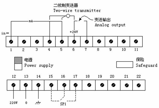
ͼ1 �DZ�����߶���ͼ Chart 1 Instrument Connection Terminal Chart | |
|
ע�� 1���������Ĭ��Ϊ4-20mA������Ҫ0-5V��1-5V��0-10V�����ڼ��˽�250����500�����ܵ�����ȡ�źš� 2������Ҫ�������ʱ���뽫6��7���Ӷ̽ӣ�����״̬������Ҫʱ����̽��ߣ���ͼ�����ɡ� |
Notes: (1) The default analog output is 4-20mA. If need 0-5V, 1-5V or 0-10V, please connect the detecting terminal with 250�� or 500�� precision resistance to extract signal. (2) If do not need analog output, please short connect 6 and 7 terminals (factory setting); if need, remove the short connection wire, and connect according to the chart. |
|
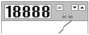
�塢��岼������������μ�ͼ2�� |
5. Panel Layout and Operation: (refer to Chart 2) | ||||||||||||||||||||||||||||||||||||||||||
|
ͼ2 ���ͼ Chart 2 Panel | |||||||||||||||||||||||||||||||||||||||||||
|
| ||||||||||||||||||||||||||||||||||||||||||
|
���趨ֵ�ĵ�������ͨ��SET���š��ĸ��������У���������:
|
The adjustment of set value can be made by the keys of SET, �� and ��, and the steps are as follows:
| ||||||||||||||||||||||||||||||||||||||||||
�ڶ����֣��������á�����У����ά���ֲ� (���Զ����DZ�������Աʹ��)
Part Two: Function Setup, Precision Calibration and Maintenance Manual
(for automation instrument technicians to use)
|
���DZ��Ǵ��������������DZ��������û����DZ����ܽ��ж������á��磬�����ֳ�״�����µ����DZ�������������������Ҫ��չ��ѹ��������Χ�����ûز�ͱ�����ʽ�ȡ���Щ�����������Զ����DZ�������Ա����ͨ�����������ӦB�˵����С� һ��B�˵����DZ����ܲ˵������� ����SET��������ʾ��ʾ����SEL���� ������000Ϊ123 ������SET�����������DZ��������ù��̣�B�˵����� |
This instrument is the intelligent instrument with microprocessor, allowing user to make the secondary setup to the instrument functions. Such as readjust the instrument anti-jamming capability according to the field condition; extend or reduce metering range according to the needs; reset return difference and alarm mode. This function setup is charged by the automation instrument technicians through entering the corresponding B menu by password. |
| ||||||||||||
|
1. B Menu (Instrument Function Menu) Setup Press ��SET�� Key, display the prompt ��SEL���� change the data 000 into 123 �� Press ��SET�� Key, and enter the instrument function setup process (B Menu). |
| |||||||||||||
|
��Ŀ Item |
���� Prompt |
����ʾ��Ϊ Change the assistant display into |
| |||||||||||
|
���뷽ʽ���� Input mode setup |
In |
���� Code |
���� Classification |
�ź����� Signal range |
���� Decimal points |
��ʾ���� Display range |
| |||||||
|
14 |
���� Linear |
4~20mA |
0��1��2��3 |
-1999~1999 |
| |||||||||
|
С����ʾλ�� Decimal display digits |
dIP |
�ɸ���ʵ����ʾ��������0��3���μ�In�� Can be set as 0��3 according to actual display range (refer to In) |
| |||||||||||
|
��ʾʼ��Ǩ�� Display initial point move |
_-�� |
����ʵ����ƫ�ƵĹ��������� Set according to the actual moving work amount |
| |||||||||||
|
�����ź���ʾ�������� Linear signal displays lower range limit |
Ldo |
����ʵ�ʹ��������ã�����4mA��Ӧ��0kPa Set according to actual work amount, such as 0kPa corresponding to 4mA |
| |||||||||||
|
�����ź���ʾ�������� Linear signal displays upper range limit |
LuP |
����ʵ�ʹ��������ã�����20mA��Ӧ��150kPa Set according to actual work amount, such as 150kPa corresponding to 20mA |
| |||||||||||
|
SP1���� SP1 setup |
SP1 |
����ʵ�ʹ�������Ҫ���ã�����120kPa�����ڳ��±��� Set according to actual work amount, such as 120kPa, used for over-heat alarming |
| |||||||||||
SP1�ز����� SP1 return difference setup |
P1h |
����ʵ�ʹ�����Ҫ�����ã�����5 kPa Set according to actual work amount, such as 5kPa |
| |||||||||||
|
SP1������ʽ SP1 operation mode |
P1c |
���� Code |
˵�� Explanation |
ʾ��ͼ Diagram |
||||||||||
|
0 |
�����������������趨�� + �ز�ֵʱ���̵���ʧ�磻 �������½��������趨��ʱ���̵����õ� When the controlled volume rises and is higher than the set point + return difference value, the relay loses power; When the controlled volume drops and is lower than the set point, the relay gets power |
Up link
Down link | ||||||||||||
|
1 |
�����������������趨�� + �ز�ֵʱ���̵���ʧ�磻 �������½��������趨�� - �ز�ֵʱ���̵����õ� When the controlled volume rises and is higher than the set point + return difference value, the relay loses power; When the controlled volume drops and is lower than the set point �C return difference value, the relay gets power |
| ||||||||||||
|
2 |
�����������������趨��ʱ���̵���ʧ�磻 �������½��������趨�� - �ز�ֵʱ���̵����õ� When the controlled volume rises and is higher than the set point, the relay loses power; When the controlled volume drops and is lower than the set point �C return difference value, the relay gets power |
| ||||||||||||
|
3 |
���������ڣ��趨�� + �ز�ֵ���趨��- �ز�ֵ��֮��ʱ���̵����õ磻����ʧ�� When the controlled volume is between (the set point + return difference value and the set point �C return difference value), the relay gets power; otherwise, loses power |
| ||||||||||||
|
�������ʼ������ Analog output initial point setup |
odo |
ͬ��ʾʼ�㣨Ldo�����õ����ݣ�����0kPa Same as the data set at the display initial point (Ldo), such as 0kPa |
���E�˵����� Refer to E Menu setup |
| ||||||||||
|
��������յ����� Analog output initial point setup |
oUP |
ͬ��ʾ�յ㣨LuP�����õ����ݣ�����150kPa Same as the data set at the display terminal point (LuP), such as 150kPa |
| |||||||||||
|
�������ʼ��У Analog output initial point calibration |
oE3 |
���š��ļ���ʹ��������ź�Ϊ4mA Press �� and �� keys to make the analog output signal as 4mA |
| |||||||||||
|
��������յ�У Analog output initial point calibration |
oE4 |
���š��ļ���ʹ��������ź�Ϊ20mA Press �� and �� keys to make the analog output signal as 20mA |
| |||||||||||
|
���ˣ��˵�������ϡ��ڡ�SEL���˵�����123Ϊ���������������˳��˵�ѭ�����ָ�����״̬�� |
Hence, the menu operation finishes. Changing 123 into other random numbers under the menu of ��SEL�� can exit the menu circulation and restore to the operation status. |
|
����E�˵����ü�����У���ɼ�����Ա���У� �DZ�����һ��һ��У��һ�Σ������DZ������ź�����ѡ����ӦУ����������£� a�� �����ź�У ����SET��������ʾ��ʾ����SEL���� ������000Ϊ159 ������SET����������У���̣�E�˵����� |
2. E Menu Setup and Precision Calibration (made by metering personnel) Make the instrument precision calibration once a year and select the corresponding calibration items according to the instrument input signal types. The steps are as follows: a) Input signal calibration Press ��SET�� Key, display the prompt ��SEL���� change the data 000 into 159 �� Press ��SET�� Key, and enter the calibration process (E Menu). |
|
У��Ŀ Calibration items |
��ʾ Prompt |
���ź����� Standard signal input |
��ʾ���ݵ���Ϊ Adjust the display data into |
| ||
|
�����ź�20mA���궨 Linear signal 20mA benchmark calibration |
E9 |
��20mA���ź� Connect to 20mA standard signal |
20.00 |
| ||
|
b�� �������У��4-20mA�������У�� ����SET��������ʾ��ʾ����SEL�� �� ��000ΪУ������123 �� ����B�˵����á�����SET����ֱ����ʾ��ʾ����odo���� |
b) Analog output calibration(4-20mA analog output calibration) Press ��SET�� Key, display the prompt ��SEL���� change the data 000 into 123 �� enter B menu setup. Press ��SET�� Key till displaying the prompt ��odo��. | |||||
|
��ʾ�� Prompt |
���� Contents |
���� Operation |
| |||
|
odo |
�������������� Analog output zero point setup |
����ʵ�ʹ��������ã�һ���ͬ���DZ��������ޣ�LuP�������ޣ�Ldo�������á�����odo=0��oUP=150 Set according to the actual work amount, and is generally same as the instrument range upper limit (LuP) and lower limit (Ldo) setup. Suah as odo=0, oUP=150 |
| |||
|
oUP |
��������յ����� Analog output terminal point setup |
| ||||
|
oE3 |
������������ Analog output zero point calibration |
��6��+24V����7(-)���Ӽ䴮��������������������źŵ���ʼ�㣬���š��ļ�У���ֱ���������Ϊ4mA Connect the ampere meter between the 6 (+24V) and 7 (-) terminals, adjust the input signal to the initial point, and press �� and �� keys to calibrate the zero point till the output current is 4mA |
| |||
|
oE4 |
��������յ�У�� Analog output terminal point calibration |
��6��+24V����7(-)���Ӽ䴮��������������������źŵ���ֹ�㣬���š��ļ�У�յ�ֱ���������Ϊ20mA Connect the ampere meter between the 6 (+24V) and 7 (-) terminals, adjust the input signal to the terminal point, and press �� and �� keys to calibrate the terminal point till the output current is 20mA |
| |||
|
c�� ��¼����У �ı������źŵ��յ㣬����������RV206ʹ��¼�����Լ�¼ֽ�յ㣻�ı������źŵ�ʼ�㣬����RV202ʹ��¼�����Լ�¼ֽʼ�㣻����У����ֱ�����յ㶼�ͼ�¼ֽ�̶��߷��ϡ� |
c) Recording precision calibration Change the input signal to the terminal point and adjust the RV206 on the master board to make the recording pen just against the terminal point of the recording paper; Change the input signal to the initial point and adjust the RV202 to make the recording pen just against the initial point of the recording paper; make the calibration repeatedly for several times till the initial and terminal points meet the scale marks of the recording paper. |